| Beam Loading - P5500 | ||||||
|---|---|---|---|---|---|---|
| Span (in) |
Max Allow. Unifor Load (lbs) |
Deflection at Uniform Load (in) |
Uniform Loading at Deflection | Lateral Bracing Reduction Factor | ||
| Span/180 (lbs) |
Span/240 (lbs) |
Span/360 (lbs) |
||||
| 24 | 3,270 | 0.04 | 3,270 | 3,270 | 3,270 | 0.99 |
| 36 | 2,180 | 0.09 | 2,180 | 2,180 | 2,180 | 0.89 |
| 48 | 1,640 | 0.15 | 1,640 | 1,640 | 1,420 | 0.77 |
| 60 | 1,310 | 0.24 | 1,310 | 1,310 | 910 | 0.67 |
| 72 | 1,090 | 0.34 | 1,090 | 950 | 630 | 0.58 |
| 84 | 940 | 0.47 | 930 | 700 | 470 | 0.51 |
| 96 | 820 | 0.61 | 710 | 530 | 360 | 0.46 |
| 108 | 730 | 0.78 | 560 | 420 | 280 | 0.42 |
| 120 | 650 | 0.95 | 460 | 340 | 230 | 0.40 |
| 144 | 550 | 1.39 | 320 | 240 | 160 | 0.36 |
| 168 | 470 | 1.89 | 230 | 170 | 120 | 0.32 |
| 192 | 410 | 2.46 | 180 | 130 | 90 | 0.30 |
| 216 | 360 | 3.07 | 140 | 110 | 70 | 0.28 |
| 240 | 330 | 3.86 | 110 | 90 | 60 | 0.26 |


Unistrut
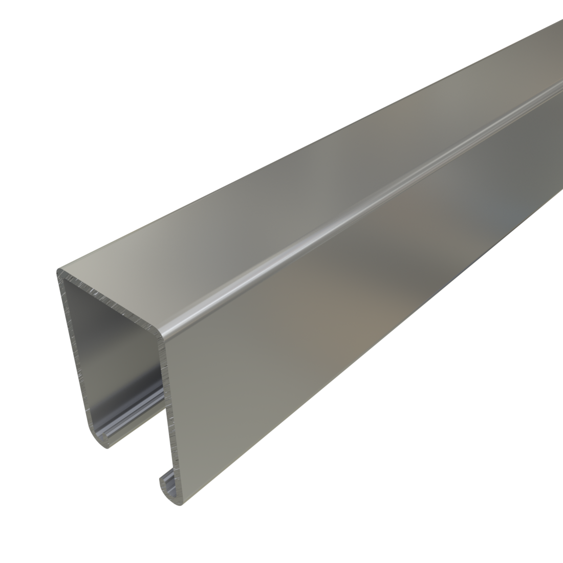
Unistrut P5500 - 1-5/8" x 2 7/16", 12 Gauge Metal Framing Strut, Solid
Length:10'
Finish:Perma-Green® III
Quantity:
CUT TO A CUSTOM LENGTH? MAY SAVE ON SHIPPING
HOW WOULD YOU LIKE IT CUT?
Some cutting jobs allow us to use ground shipping rather than LTL, yielding significant freight savings. A customer service associate will contact you to confirm the cut list and shipping and freight costs prior to finalizing your order. eg - 4 cuts per stick x 5ft per section
12 Gauge Solid Strut Channel P5500 is commonly used for trapeze supports, seismic bracing, ceiling grids, pipe, conduit, duct and cable tray supports, racks, and other general framing. For application examples, refer to our Application Showcase.
Features:
- Product dimensions are 1 5/8" wide x 2 7/16" tall x 12 ga. thick, solid.
- Punched holes are also available for ease of installation
- The advantage of a deeper, heavier gauge profile is to support heavier loads and mitigate deflection under load.
- OPM pre-approved for seismic applications
- UL and CSA listed
- Our P5500 is available in the following finishes: Pre-Galvanized (PG), Unistrut Defender (DF), Hot-Dip Galvanized (HG), Plain (PL), Green (GR), Zinc Dichromate (ZD), Stainless Steel (SS or ST) and Aluminum (EA).
- Made in the USA

Specifications
Beam Loading
Column Loading
| Column Loading - P5500 | |||||
|---|---|---|---|---|---|
| Unbraced Height (in) |
Allowable Load at Slot Face (lbs) |
Max Column Load Applied at C.G. | |||
| K=0.65 (lbs) | K=0.80 (lbs) | K=1.0 (lbs) | K=1.2 (lbs) | ||
| 24 | 4,640 | 13,840 | 12,570 | 10,840 | 9,190 |
| 36 | 3,970 | 11,050 | 9,190 | 7,030 | 5,370 |
| 48 | 3,180 | 8,420 | 6,390 | 4,620 | 3,630 |
| 60 | 2,550 | 6,250 | 4,620 | 3,450 | 2,780 |
| 72 | 2,120 | 4,790 | 3,630 | 2,780 | 2,260 |
| 84 | 1,810 | 3,890 | 3,010 | 2,330 | 1,910 |
| 96 | 1,580 | 3,290 | 2,580 | 2,020 | 1,650 |
| 108 | 1,400 | 2,860 | 2,260 | 1,770 | 1,440 |
| 120 | 1,270 | 2,530 | 2,020 | 1,580 | KL/r>200 |
| 144 | 1,060 | 2,070 | 1,650 | KL/r>200 | KL/r>200 |
| 168 | 920 | 1,750 | 1,380 | KL/r>200 | KL/r>200 |
Elements of Section
| Elements of Section - P5500 | ||
|---|---|---|
| Area of Section | 0.726 in2 (4.7 cm2) | |
| Axis 1-1 | Axix 2-2 | |
| Moment of Inertia (I) | 0.522 in4 (21.7 cm4) | 0.334 in4 (13.9 cm4) |
| Section Modulus (S) | 0.390 in3 (6.4 cm3) | 0.411 in3 (6.7 cm3) |
| Radius of Gyration (r) | 0.848 in (2.2 cm) | 0.679 in (1.7 cm) |
General Specifications
Standard Lengths:
- 10 feet: 10' or 10’ 1/8” (3.05m) ± 1/8" (3 mm)
- 20 feet: 20' or 20’ 3/8” (6.11m) ± 1/8" (3 mm)
Special Lengths:
- Available with a tolerance of ±1/8" (3 mm). Request quote.
- All beam and column load data pertains to carbon steel and stainless steel channels.
- Load tables apply only to UNISTRUT brand channel. Look for "UNISTRUT" on the product.
- Load tables and charts are constructed to be in accordance with the SPECIFICATION FOR THE DESIGN OF COLD-FORMED STEEL STRUCTURAL MEMBERS 2007 EDITION published by the AMERICAN IRON AND STEEL INSTITUTE USING ASD METHOD.
- Loads are based on 33 ksi steel cold formed to 42 ksi.
- Safety Factor to Yield Strength is 1.67 for Beam Loads and 1.80 for Column Loads.
- Beam loads are based on a simple beam and are given as a total uniform load (W) in pounds. For proper calculation procedures, refer to our Beam Load Calculation Guide under Resources.
- For bearing loads, reference our Bearing Loads Page.
Materials & Finishes
Materials & Finishes - Standard:
- Pregalvanized (PG): Conforms to ASTM A653 SS GR 33, G90.
- Unistrut Defender (DF): Conforms to ASTM A1046 SS GR 33
- Hot Dip Galvanized (HG): Steel conforms to ASTM A1011 SS GR 33, Finish conforms to ASTM A123
- Perma-Green (GR): Steel conforms to ASTM A1011 SS GR 33, E-Coat finish
- Perma-Gold (ZD): Steel conforms to ASTM A1011 SS GR 33, Finish conforms to ASTM B633, Type II SC3
- Plain (PL): Conforms to ASTM A1011 SS GR 33
- Stainless Steel, Type 304 (SS): ASTM A240, Type 304 *
- Stainless Steel, Type 316 (ST): ASTM A240, Type 316 *
- Aluminum (EA): ASTM B221, Type 6063-T6 (Extruded) *
* These materials have different physical properties and performance characteristics. Please contact us for design support.