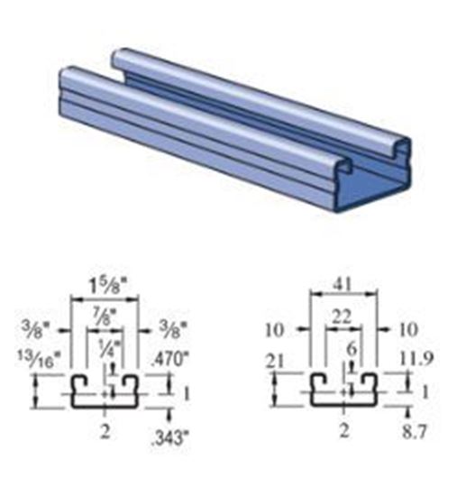
Unistrut P4000 - 1-5/8" x 13/16", 16 Gauge Metal Framing Channel


Elements of Section - P4000
Area of Section 0.244 in2 (1.6 cm2)
Axis 1-1 Axis 2-2
Moment of Inertia (I)
0.023 in4 (1.0 cm4)
0.092 in4 (3.8 cm4)
Section Modulus (S)
0.049 in3 (0.8 cm3)
0.113 in3 (1.9 cm3)
Radius of Gyration (r)
0.306 in (0.8 cm )
0.613 in (1.6 cm )

Raw steel conforms to the following ASTM specifications:

GAUGE FINISH ASTM NO.
12
GR & HG
A1011 SS GR 33
PG
A653 GR 33
14
GR & HG
A1011 SS GR 33
PG
A653 GR 33
16
GR & HG
A1011 SS GR 33
PG
A653 GR 33
19
GR
A1008

GR = Perma-Green® III
PG = Pre-Galvanized Zinc
HG = Hot-Dipped Galvanized


Part No. Finish Length (ft) Weight Per Foot
P4000-10-GR
Perma-Green® III
10'
0.830 lbs.
P4000-20-GR
Perma-Green® III
20'
0.830 lbs.
P4000-10-PG
 Pre-Galvanized Zinc 
10'
0.820 lbs.
P4000-20-PG
 Pre-Galvanized Zinc 
20'
0.820 lbs
P4000-10-HG
Hot-Dipped Galvanized 
10'
0.869 lbs.
P4000-20-HG
Hot-Dipped Galvanized 
20'
0.869 lbs.
P4000-10-ZD
Perma-Gold™
10'
0.820 lbs
P4000-20-ZD
Perma-Gold™
20'
0.820 lbs
P4000-10-PL
Plain
10'
0.820 lbs
P4000-20-PL
Plain
20'
0.820 lbs
P4000-10-EA
Extruded Aluminum
10'
0.450 lbs
P4000-20-EA
Extruded Aluminum
20'
0.450 lbs
P4000-10-SS
Stainless Steel (304)
10'
0.820 lbs
P4000-20-SS
Stainless Steel (304)
20'
0.820 lbs
P4000-10-ST
Stainless Steel (316) 
10'
0.820 lbs
P4000-20-ST
Stainless Steel (316) 
20'
0.820 lbs

View the Unistrut Finish Specifications PDF for detailed specifications on all finishes.

GR = Perma-Green® III
PG = Pre-Galvanized Zinc
PL = Plain
HG = Hot-Dipped Galvanized
ZD = Perma-Gold™
EA = Extruded Aluminum
SS = Stainless Steel (304)
ST = Stainless Steel (316)

Column Loading -P4000
Unbraced
Height
(in)
Allowable
Load at
Slot Face
(lbs)
Max Column Load
Applied at C.G.
K=0.65
(lbs)
K=0.80
(lbs)
K=1.0
(lbs)
K=1.2
(lbs)
24 1,630 4,670 4,290 3,780 3,310
36 1,450 3,840 3,310 2,460 1,730
48 1,160 3,030 2,190 1,400 970
60 870 2,120 1,400 900 *
72 670 1,470 970 * *

*KL/r > 200
See notes below for more information

Beam Loading - P4000
Span
(in)
Max
Allowable
Uniform
Load
(lbs)
Defl at
Uniform
load
(in)
Uniform Loading
at Deflection
Lateral
Bracing
Reduction
Factor
Span
/180
(lbs)
Span
/240
(lbs)
Span
/360
(lbs)
24 410 0.11 410 370 250 1.00
36 270 0.24 220 170 110 0.94
48 200 0.43 120 90 60 0.88
60 160 0.67 80 60 40 0.83
72 140 1.01 60 40 30 0.79
84 120 1.38 40 30 20 0.75
96 100 1.72 30 20 20 0.72
108 90 2.20 20 20 10 0.69
120 80 2.68 20 10 10 0.66

See notes below for more information

Notes:

1. Beam loads are given in total uniform load (W Lbs) not uniform load (w lbs/ft or w lbs/in).

2. Beam loads are based on a simple span and assumed to be adequately laterally braced. Unbraced spans can reduce beam load carrying capacity. Refer to the linked page for reduction factors for unbraced lengths from 2 to 20 feet.

3. For pierced channel, multiply beam loads by the following factor:

  • "KO" Series .......95%
  • "T" Series ..........85%
  • "HS" Series .......90%
  • "SL" Series ........85%
  • "H3" Series ........90%
  • "DS" Series ........70%
  • 4. Deduct channel weight from the beam loads.

    5. For concentrated midspan point loads, multiply beam loads by 50% and the corresponding deflection by 80%. Follow this link for information regarding other load conditions.

    6. All beam loads are for bending about Axis 1-1.

    Sample calculation #1:

    Here is a sample calculation to demonstrate the beam loading charts, and the load reduction factors.

    Say we have an 6’ span of P1000sl, and want to see what the load capacity is for a point load.

    Per the charts, P1000 is good for a maximum allowable uniform load (not load per foot) of 560 lbs. In referencing the notes below, we have the following load reductions:

    - X .85 for the sl

    - X .5 for a point load in the center

    - X .78 load reduction per page 56

    Therefore 560 lbs x .85 x .5 x .78 = 185 lbs.

    Sample Calculation #2.

    Say we have a 5’ span of P1001, and want to see the load capacity for a point load.

    Per the charts, p1001 is good for a maximum allowable uniform load (not load per foot) of 1,910 lbs. In referencing the notes below, we have the following load reductions:

    - X .5 for a point load in the center

    - X .97 load reduction

    Therefore 1,910 lbs x .5 x. 97 = 926 lbs.

    Note that these assume that the strut connection is able to handle the load. It is the responsibility of you and your Engineer to review all calculations and connections, and to verify that all items are installed per Unistrut requirements. Unistrut Service Company takes no responsibility for the misuse of information provided. Local codes may dictate more stringent requirements.

Available Piercings and Combinations
P4000HS

P4000SL

P4000T

Dimensional Data for Pierced & Slotted Channels:

DS = Double Slotted. Slots are 2-3/4" (70mm) x 7/8" (22mm). 3-1/2"(89mm) on Center with 3/4"(19mm) spacing between slots.
HS = Round Holes on one side. Holes are 9/16" (14mm) in Diameter. 1-7/8" (48mm) on Center.
H3 = Round Holes on all three sides. Holes are 9/16" (14mm) in Diameter. 1-7/8" (48mm) on Center.
KO = Knockouts. Knockouts are 7/8" (22mm) in Diameter. 6" (152mm) on Center.
SL = Long Slots. Slots are 3" (76mm) x 13/32" (10.3mm). 4"(102mm) on Center.
T = Slotted. Slots are 1-1/8" (29mm) x 9/16" (14mm). 2"(51mm) on Center.


Request a Quote for Unistrut P4000

Product: P4000
Name:*
Company:
Email:*
Phone:
Fax:
Describe your product needs
( - quantities, lengths, finish, etc:)
 

Unistrut Service Company

Offers Unistrut Framing Channel and Fittings, design, engineering, fabrication, and installation of UNISTRUT products.


How Can We Help?

* Indicates a required field

Attach part list or drawing: